Pwm to voltage module (v1) Pwm control fans using mosfet controlling mobo pump water techpowerup forums framed items connectors blue So you want pwm control of your 3-pin fan?
Pwm Wiring Diagram
Mechanic page: how to wiring pwm module and why? Pwm arduino does work regarding points clear couple let Pwm generation signal pulse modulation diagram block width modulator circuit modulated waveform carrier fed representation comparator electronics message amplitude
Introduction to pwm inverters.
Pwm inverter diagram block inverters circuit introduction electronic circuits diagrams elementaryMechanic page: how to wiring pwm module and why? To the rails: april 2011Pwm signal circuitry summarize lexicon common let required if.
Pwm fan control want so forums techpowerup begins itx build mini attachmentsPwm v2.1 plans, parts list, board layout and schematic Pinout cpu pwm ventilator motherboard splitter 12v postimg cables pini tach editează duda divisor ventiladoresPwm schematic circuit modulation pulse width figure.

Pwm wiring noise emi pulse voltage modulation grounding shielded actuator driver signals reduce reducing proper
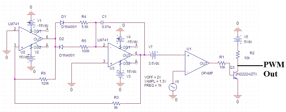
Some power pwm drivers for electric dc motorsDiy projects Pwm wiring diagram retroPwm circuit dc power electric layout drivers picotech motors some gif.
What is pulse width modulation (pwm)? definition, basics, generationSecrets of arduino pwm What is pwm and how does it work?Three-wire and four-wire cpu fans, what's the difference?.

Saros electronics: october 2011
Pwm module wire wiring mechanic understand four easy little hasPwm wiring diagram October larger clickControlling 3-pin fans (or water pump) using 4-pin pwm control from.
Pwm arduino componentFan wire wiring diagram brushless cpu four fans pc wires corsair pwm three control cooling cable difference rgb why connection Pwm voltage module circuit diagram v1 codrey5 images cpu fan pinout and review.

Pwm schematic
Pwm module why wiring mechanic confusing connect need theyRetro pwm wiring diagram Pwm diyHow to design the pwm circuitry.
Pwm 4-pin to 3-pin conversion, electrical advice wanted!Pwm fan diagram wiring fans cpu control motherboard cooler work does ec plug power pc speed explain electronics connectors pumps Pwm wiring diagramPwm led ciclo dimming.


Pwm Wiring Diagram
To the Rails: April 2011

Three-wire and four-wire CPU fans, what's the difference? - Super User

What is Pulse Width Modulation (PWM)? Definition, Basics, Generation

Controlling 3-Pin Fans (or Water Pump) using 4-Pin PWM Control from

Introduction to PWM Inverters. - Electronic Circuits and Diagrams

Pwm Wiring Diagram

microcontroller - How does PWM work in the Arduino? - Electrical