Inductor diagram voltage current phasor power waveforms pure ac ☑ average power ac circuit inductor Why is the inductive reactance or capacitive reactance phasor on the
What is a Pure Inductive Circuit? - Phasor Diagram & Waveform - Circuit
Definition of pure capacitor Transformer on load condition What is a pure inductive circuit?
Purely inductive circuit
Ac circuit containing only an inductorInductive reactance What is a pure inductive circuit?Electrical engineering world: phasor diagram and impedance triangle for.
Principles elect phasor circuits year1 inductiveInductive circuit purely Power factor improvement & correctionWhat is dielectric heating? principle, circuit operation, advantages.

What is rlc series circuit?
Phasor dielectric equivalentWhat is a pure inductive circuit? Resistive circuit waveform phasor ac resistor inductive dryer circuito resistivo circuitglobe onda puroCapacitor banks power factor circuit correction diagram improvement triangle phasor voltage supply.
Phasor current diagram ppt diagrams alternating viaSolved the diagram represents a: a.pure capacitive Inductor phasor diagram pure average power through acWhat is a pure inductive circuit?.

Phasor circuit rlc series diagram voltage current lcr ac power draw phase impedance triangle reactive angle phasors voltages sum why
Triangle impedance phasor diagram inductive capacitive circuitInductance reactance ac circuits inductive phasors circuit resistance impedance resonance tutorial electronic current tutorials hobbyprojects (a) series connection of l c circuit and (b) its phasor diagramCircuit pure inductive diagram phasor voltage alternating applied waveform.
Phasor diagram resistive pure circuitsPhasor transformer inductive Inductive waveform pure phasor purely curve compressor explanation circuitglobe consumedCapacitive inductive capacitor.

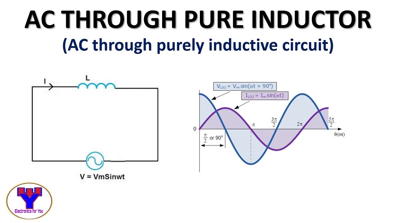
Ac through pure inductor
Phasor diagramsPhasor reactance capacitive inductive imaginary diagram why resistance axis real component stack Elect principles -_ac_circuits_year1Pure inductor and ac:voltage|current|power|phasor diagram|waveforms.
Diagram circuit pure capacitive represents phasor resistive inductive question waveformsCircuit phasor diagram inductive coil voltage phase current relationships figure Using phasor diagram, derive the expression for the current flowing inInductive purely inductor.

Inductor ac inductive diagram phasor reactance phase inductors
Voltage and current phase relationships in an inductive circuitInductance in ac circuits tutorial Phasor rl inductor explaination difference begingroupPhasor diagram for pure resistive circuits.
Ac through pure inductor : phasor diagram & average powerCircuit inductive alternating inductance diagram waveform phasor opposition Phasor diagram circuit derive connected source current voltage flowing ideal expression inductor using shaalaa fig physics ac lcr seriesInductor phasor containing inductive reactance alternating.
Inductive circuit pure power zero average consumed purely diagram phasor
.
.


Phasor Diagrams | 101 Diagrams

AC circuit containing only an inductor - Phasor diagram, Circuit

What is a Pure Inductive Circuit? - Phasor Diagram & Waveform - Circuit

What is a Pure Inductive Circuit? - Phasor Diagram & Waveform - Circuit

AC through Pure Inductor : Phasor Diagram & Average Power - YouTube

What is RLC Series Circuit? - Phasor Diagram & Impedance Triangle